
www.industryemea.com
19
'26
Written on Modified on
Power Test Systems Launches 900 EX Power Bridge
Webasto introduces the 900 EX Power Bridge, an integration solution that couples existing test units to scale total system output up to 1500 V and 500 kW.
www.webasto.com
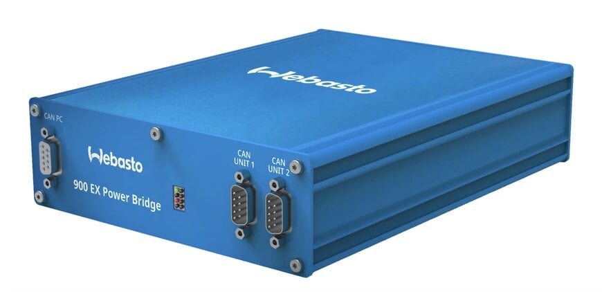
Webasto has launched the 900 EX Power Bridge, a specialized integration hardware platform engineered to support higher voltage battery testing across automotive, off-road, marine, rail, and stationary energy storage applications. The system allows users to structurally link standalone test equipment to meet the requirements of next-generation high-voltage platforms without expanding control complexity.
System Integration and Performance Scaling
The expansion of high-voltage electric vehicle (EV) battery packs and commercial grid-tied storage architectures requires advanced laboratory hardware capable of validating safety and operational limits under accelerated performance loads. The 900 EX Power Bridge addresses these demands by enabling test engineers to combine two independent 900 EX units into a single synchronized test network.
By executing a series coupling arrangement, the hardware scales total system performance thresholds up to 1500 VDC and 500 kW. This configuration permits laboratories and automotive suppliers to enhance their high-voltage validation capabilities while maximizing the utility of their pre-existing testing infrastructure.
Operational Consistency and Field Control
The coupling solution is designed to maintain strict operational continuity within existing laboratory frameworks. When linked via the integration module, each individual 900 EX unit retains its standalone operating logic, performance characteristics, and unit behavior.
The system preserves established asset management workflows through several targeted software and mechanical features:
- Interface Compatibility: The module operates natively with Webasto's standard Controller Area Network (CAN) interface, allowing existing high-frequency CAN-based control software to manage the coupled units automatically.
- Maintenance Maintenance: The configuration introduces no new calibration procedures, secondary maintenance tools, or field training tracks, as standard standalone servicing guidelines continue to apply directly to the dual-unit setup.
- Control Responsiveness: The integrated system preserves high-frequency control loops and signal responsiveness parameters, ensuring consistent parameter validation during fast dynamic transitions.
Independent engineering laboratories, such as Excel Engineering, have deployed the system to handle 1500 V platform validation requirements. The setup allows operators to implement high-frequency control scripts and adapt to evolving customer evaluation schedules without modifying central control panel workflows or altering localized laboratory safety envelopes.
Additional Context
This section details technical specifications not included in the original news release.
Industrial battery cyclers are complex, bidirectional power electronic systems configured to source electrical current during simulated charging cycles and sink current back into the utility grid via regenerative energy recovery loops during discharge sequences. High-power cyclers like the 900 EX generally feature internal interleaved insulated-gate bipolar transistor (IGBT) topologies or silicon carbide (SiC) metal-oxide-semiconductor field-effect transistor (MOSFET) switching blocks arranged in multi-channel configurations. To scale operational voltage boundaries beyond the physical dielectric breakdown limit of a single unit's semiconductor stack, two distinct power modules must be connected in a series circuit configuration.
Linking independent bidirectional power supplies in series introduces severe electrical control challenges, primarily focused on voltage balancing and preventing transient synchronization lag. If one unit switches its internal power stage slightly faster than the adjacent unit during a high-frequency pulse step, an instantaneous voltage imbalance occurs across the intermediate DC bus. This transient state can subject the lagging unit to localized overvoltage stress, triggering automated overvoltage protection (OVP) faults and causing unintended system shutdowns.
To overcome this, the integration bridge employs hardware-level synchronization lines that bypass standard fieldbus latency, locking the internal pulse-width modulation (PWM) carrier waves of both units to a shared master clock. This configuration guarantees that current slew rates—which reach high rates during transient battery simulation profiles—are executed concurrently by both power stages, minimizing voltage ripple and maintaining control precision at higher voltage levels.
Edited by Romila DSilva, Induportals Editor, with AI assistance.
