
www.industryemea.com
30
'12
Written on Modified on
Taking the Pain Out of Mathematics
Have you ever sat at a desk sometime in the small hours of the morning, bent over a lukewarm cup of coffee, trying to make sense of a block diagram along with a notebook full of mathematical equations derived weeks ago, needing to make final changes to a simulation model due at 9 a.m.? Regardless of whether you work in automotive engineering, biomechanical systems, spacecraft mechanisms, mechatronic multi-domain systems, or micro-robotics, model-based development promises to yield higher quality designs in less time. Laurent Bernardin, Chief Scientist, Maplesoft
High-fidelity computer-based models of physical engineering systems are created and then simulated to predict the behavior of the system before physical prototypes are built. Problematic behaviors can be isolated in the early stages of the process, meaning that solutions can be developed before the physical hardware is actually built. Depending on the project, this can save days or weeks as well as real money.
However, traditional software tools to help with this process have not been able to keep up with increasingly more complex project requirements. In particular, much of the mathematical background work still needs to be done by hand, which is an error-prone and time-consuming endeavor.
Since the birth of the digital computer in the 1960s, early simulation models were hand-coded, typically in Fortran. Soon afterwards, various numeric solvers were developed to avoid having to start each new project from scratch. Eventually, the introduction of low-cost personal computers and graphical user interfaces in the 1980s led to the appearance of the block diagram modeling paradigm. Many more engineers could now develop dynamic system models on their computers.
The block diagram environment represented a true revolution for modeling and simulation. For the first time, engineers could produce models on their desktops by simply “wiring” together block components that represented the mathematics of a physical model or control system, without having to write a single line of code and, hence, at a fraction of the time and cost of hand-coded simulations.
However, these traditional modeling tools force engineers to spend a great deal of time working with the mathematics representing their system, rather than developing, simulating, and evaluating their designs. The signal-flow concept upon which they are based is adequate for addressing the challenges of numeric simulation, but the modeling environment they present is non-intuitive and difficult to use. Signal-flow design works very well with control systems design but quickly reaches its limits when applied to physical system modeling.
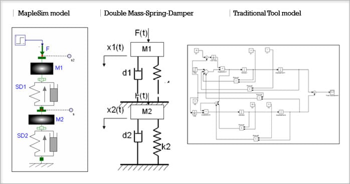
Further, before engineers can even begin to use these traditional modeling tools, the physical system itself must be manipulated into a form that the software recognizes. This generally means that engineers must perform tedious manual derivations of the system equations, a process that is time consuming, error prone, and requires advanced mathematical knowledge. For example, even when working with something as simple as a spring-mass-damper system, engineers must first draw the free-body diagram and extract from it mathematical relationships between the physical components, derive the differential equations for the system, convert them to integral form, and finally break them down to represent blocks. In addition, the resultant block diagram looks nothing like the original system representation, making it hard to comprehend and make changes. Several pages of derivation are required just to go from a free-body diagram to the simple differential equation (as in Image4). Just imagine how complex this becomes if you need to model a hybrid electric vehicle!
A Better Way…
Luckily, we are at the dawn of a new revolution. A new, more intuitive approach to physical modeling and simulation is emerging, where the mathematical derivations are handled automatically in the background. Symbolics-based physical modeling tools, like the multi-domain simulation software MapleSim from Maplesoft, let you represent the system graphically, using intuitive components such as gears, moving joints, pneumatic tires, or electric circuit components, making the models easier to build and understand. Engineering designs are described using components that represent their actual physical counterparts: electric circuits are built using resistors and inductors, and mechanical transmissions are built with gear sets and drive shafts.
Best of all, model equations are automatically generated and simplified, yielding concise models and high-speed simulations of sophisticated systems. All of the necessary relational, physical, and mathematical information for complex systems is automatically captured and managed, making it easier to develop efficient, high-fidelity models. The use of symbolics-based modeling tools is not predicated on one’s knowledge of advanced mathematics, but on the inherent talent of engineers to visualize how physical components connect and interact in real systems. Thus, the learning curve is much lower than that of signal-flow tools. Engineers can focus on the creative design process rather than having to deal with manual mathematical calculations and reference manuals.
Example Application: Dynamics of an Ice Tank Carriage
Manoeuvring through ice-covered waters requires a special type of ship, commonly known as an icebreaker. Before an icebreaker is constructed, the hull design is rigorously tested for its ice breaking capabilities in an ice tank. This is a refrigerated water tank in which a scale model of the ship’s hull is pulled by a gantry carriage through a layer of formed ice.
In one test situation, the speed of the model ship was found to become hard to control with adequate precision when the gantry carriage was operating at low speeds. The engineers discovered that the force generated by the ship’s hull when breaking ice induced backlash within the gearbox of the gantry carriage. In an attempt to compensate for the backlash, the controller caused the speed of the model ship to overshoot and then undershoot, causing damage to the test rig. MapleSim was used to create a high-fidelity physical model of the ice tank system and identify a mechanism to alleviate the backlash inherent in the design of the gearbox. The solution involved generating a back-tension to avoid the gear backlash.
The proposed solution was validated quickly, efficiently, and with minimal cost. Since the design was verified in advance, engineers were confident that only a single facility shutdown was required to make the necessary modifications. The short time required for model formulation, solution validation, and implementation of modifications meant that the testing facility was reopened sooner than would have been possible with other approaches.
With the constant need to remain current in today’s increasingly competitive landscape, engineers in all industries will benefit from these new symbolic physical modeling tools. Companies are working hard to meet the ever-growing need to increase productivity and drive innovation, while maintaining high quality standards. Virtual prototyping is an essential tool to speed up design cycles and replace expensive hardware prototypes by physical models that are used to simulate behavior and gain insight into new designs. By taking advantage of the next generation of multi-domain physical modeling and simulation tools, engineers are freed from tedious derivations and routine calculations and are able to focus their skills on creating that elusive competitive advantage to help their companies succeed.
Image3.jpeg: Unlike traditional tools, MapleSim’s physical components better represent how real-world systems interact, so models look more like a schematic of the real system.
Image1.jpeg: MapleSim graphical working environment
Image2.jpeg: Icebreaker moving through icy waters
However, traditional software tools to help with this process have not been able to keep up with increasingly more complex project requirements. In particular, much of the mathematical background work still needs to be done by hand, which is an error-prone and time-consuming endeavor.
Since the birth of the digital computer in the 1960s, early simulation models were hand-coded, typically in Fortran. Soon afterwards, various numeric solvers were developed to avoid having to start each new project from scratch. Eventually, the introduction of low-cost personal computers and graphical user interfaces in the 1980s led to the appearance of the block diagram modeling paradigm. Many more engineers could now develop dynamic system models on their computers.
The block diagram environment represented a true revolution for modeling and simulation. For the first time, engineers could produce models on their desktops by simply “wiring” together block components that represented the mathematics of a physical model or control system, without having to write a single line of code and, hence, at a fraction of the time and cost of hand-coded simulations.
However, these traditional modeling tools force engineers to spend a great deal of time working with the mathematics representing their system, rather than developing, simulating, and evaluating their designs. The signal-flow concept upon which they are based is adequate for addressing the challenges of numeric simulation, but the modeling environment they present is non-intuitive and difficult to use. Signal-flow design works very well with control systems design but quickly reaches its limits when applied to physical system modeling.
Further, before engineers can even begin to use these traditional modeling tools, the physical system itself must be manipulated into a form that the software recognizes. This generally means that engineers must perform tedious manual derivations of the system equations, a process that is time consuming, error prone, and requires advanced mathematical knowledge. For example, even when working with something as simple as a spring-mass-damper system, engineers must first draw the free-body diagram and extract from it mathematical relationships between the physical components, derive the differential equations for the system, convert them to integral form, and finally break them down to represent blocks. In addition, the resultant block diagram looks nothing like the original system representation, making it hard to comprehend and make changes. Several pages of derivation are required just to go from a free-body diagram to the simple differential equation (as in Image4). Just imagine how complex this becomes if you need to model a hybrid electric vehicle!
A Better Way…
Luckily, we are at the dawn of a new revolution. A new, more intuitive approach to physical modeling and simulation is emerging, where the mathematical derivations are handled automatically in the background. Symbolics-based physical modeling tools, like the multi-domain simulation software MapleSim from Maplesoft, let you represent the system graphically, using intuitive components such as gears, moving joints, pneumatic tires, or electric circuit components, making the models easier to build and understand. Engineering designs are described using components that represent their actual physical counterparts: electric circuits are built using resistors and inductors, and mechanical transmissions are built with gear sets and drive shafts.
Best of all, model equations are automatically generated and simplified, yielding concise models and high-speed simulations of sophisticated systems. All of the necessary relational, physical, and mathematical information for complex systems is automatically captured and managed, making it easier to develop efficient, high-fidelity models. The use of symbolics-based modeling tools is not predicated on one’s knowledge of advanced mathematics, but on the inherent talent of engineers to visualize how physical components connect and interact in real systems. Thus, the learning curve is much lower than that of signal-flow tools. Engineers can focus on the creative design process rather than having to deal with manual mathematical calculations and reference manuals.
Example Application: Dynamics of an Ice Tank Carriage
Manoeuvring through ice-covered waters requires a special type of ship, commonly known as an icebreaker. Before an icebreaker is constructed, the hull design is rigorously tested for its ice breaking capabilities in an ice tank. This is a refrigerated water tank in which a scale model of the ship’s hull is pulled by a gantry carriage through a layer of formed ice.
In one test situation, the speed of the model ship was found to become hard to control with adequate precision when the gantry carriage was operating at low speeds. The engineers discovered that the force generated by the ship’s hull when breaking ice induced backlash within the gearbox of the gantry carriage. In an attempt to compensate for the backlash, the controller caused the speed of the model ship to overshoot and then undershoot, causing damage to the test rig. MapleSim was used to create a high-fidelity physical model of the ice tank system and identify a mechanism to alleviate the backlash inherent in the design of the gearbox. The solution involved generating a back-tension to avoid the gear backlash.
The proposed solution was validated quickly, efficiently, and with minimal cost. Since the design was verified in advance, engineers were confident that only a single facility shutdown was required to make the necessary modifications. The short time required for model formulation, solution validation, and implementation of modifications meant that the testing facility was reopened sooner than would have been possible with other approaches.
With the constant need to remain current in today’s increasingly competitive landscape, engineers in all industries will benefit from these new symbolic physical modeling tools. Companies are working hard to meet the ever-growing need to increase productivity and drive innovation, while maintaining high quality standards. Virtual prototyping is an essential tool to speed up design cycles and replace expensive hardware prototypes by physical models that are used to simulate behavior and gain insight into new designs. By taking advantage of the next generation of multi-domain physical modeling and simulation tools, engineers are freed from tedious derivations and routine calculations and are able to focus their skills on creating that elusive competitive advantage to help their companies succeed.
Image3.jpeg: Unlike traditional tools, MapleSim’s physical components better represent how real-world systems interact, so models look more like a schematic of the real system.
Image1.jpeg: MapleSim graphical working environment
Image2.jpeg: Icebreaker moving through icy waters
