www.industryemea.com
15
'24
Written on Modified on
Yamaha: Boosting SMT Throughput with Single- and Dual-Lane Upgrades
Understanding the true location of SMT-line bottlenecks helps manufacturers invest wisely when the time comes to upgrade.
In the pursuit of improved productivity, any surface-mount assembly line can contain a bottleneck that presents a barrier to increasing throughput. Adding an extra mounter is an obvious way to overcome this, although a faster machine is another option. On the other hand, it could be time to upgrade the line to a dual-lane setup.
The optimum decision can depend on the typical board cycle time and variety of components to be placed on each PCB. Also, relieving the placement bottleneck is certain to highlight the limitations of other equipment in the line, such as the reflow oven. So the response to this immediate need for speed should be sensitive to the factory’s future investment plans.
More Mounters
Inserting an extra mounter in the line introduces additional placement capacity, although the improvement may be less than expected. A pair of mounters placed inline extends the effective distance each board must travel to reach the next process, which increases the total PCB transfer losses. Inserting the extra mounter also increases the overall footprint of the line by one extra unit, which can be a problem if available floorspace is limited.
Going Dual Lane
For greater line performance within a limited footprint, moving to a dual-lane line can offer advantages. With two lanes and two placement heads, a two-beam, dual-lane mounter can mathematically double the line’s placement capacity. In practice, however, the performance gain may be lower. Also, two traversing units are needed: one to transfer boards from a single-lane printer into the dual-lane mounter and another to transfer populated boards from the mounter into the reflow oven.
The dual-lane mounter can be used in either of two modes. In parallel mode, two boards are loaded simultaneously and populated at the same time as the two placement heads operate independently. The transfer time, to bring the boards into the mounter and apply tooling ready for component placement must be considered when calculating the overall cycle time. When operating in parallel mode, only one side of the feeder bank can be used for each lane of boards. This can be a disadvantage when building boards that have a large mix of component types.
On the other hand, the mounter can operate in alternate mode. In this case, the board in one lane is populated while the second lane handles transferring and fixing the next board. This effectively reduces the board transfer time overhead to zero. However, the two heads cannot operate continuously as each must wait to avoid interference with the other.
Compare Performance
Noting that a typical board transfer time is usually about two or three seconds, alternate mode can achieve a faster cycle time when a small number of components need to be placed. This is when saving the board transfer time has the most significant impact on reducing the overall cycle time.
As the number of parts to be mounted increases, the time spent placing components represents a greater proportion of the cycle time. As a result, the advantage by saving the transfer time in alternate mode diminishes. In practice, if the cycle time is greater than about 15 seconds, the losses accumulated in alternate mode while either head is not doing work in order to avoid head interference outweigh the savings achieved by negating board transfer time. If this is the case, parallel mode can offer greater productivity, subject to adequate feeder access.
Another Way
Despite the potential speed improvement in either mode, a dual-lane mounter may not be the best solution for a single-lane line. In practice, the mounter's production capacity is determined not by the number of lanes, but by utilization of the placement head. The greatest productivity depends on keeping placement heads active for as much of the cycle time as possible.
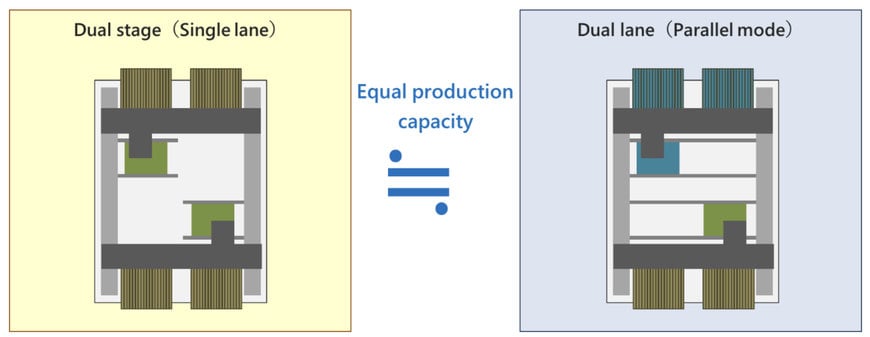
With this in mind, a single-lane, dual-stage mounter with two placement heads can have the same theoretical capacity as a dual-lane machine in parallel mode (figure 1), while also allowing access to both front and rear feeders.
The board transfer losses include extra time for lane splitting, which is done inside the mounter. On the other hand, no traversing unit is needed to take boards from the printer. The waiting time to avoid head interference is zero and the compact footprint equivalent to a single-lane mounter ensures the total distance travelled for pick and place is short.
Overall, if there are no special conditions attached to the type of boards being assembled, a dual-stage, two-head mounter can boost productivity more effectively than introducing a dual-lane mounter or two conventional single-beam machines.
Understanding the Bottleneck
When component mounting is the process restricting line performance, upgrading the mounting capacity is the appropriate response. However, if another process is causing the bottleneck, increasing component-placement performance can be a wasted investment. To illustrate this point, consider an SMT line as in figure 2, with process cycle times as shown. Here, the first mounter is indeed the bottleneck and is restricting the line cycle time to 40 seconds.
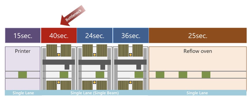
Mounter restricting SMT line performance.
Avoid Idle Mounters
In the example of figure 3, upgrading to single-lane dual-stage has cut the mounting time and the reflow soldering process now defines the line cycle time. This time cannot be reduced, because the reflow profile has a fixed duration. In the illustration, each mounter is significantly faster than the cycle time limited by reflow and is idle for several seconds per cycle. The investment in mounting speed is effectively wasted.
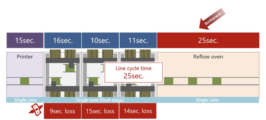
The reflow process restricts SMT line cycle time.
An effective cycle time of 25 seconds is quite typical for reflow soldering. If the mounters in the line are already faster than this, the reflow process is the most likely bottleneck. Upgrading single-lane reflow with a dual-lane oven cuts the cycle time to 12.5 seconds, as figure 4 shows. In this case, dual-lane component mounters can interface efficiently with the reflow oven. A traversing unit is needed between a single-lane printer and the dual-lane mounters.
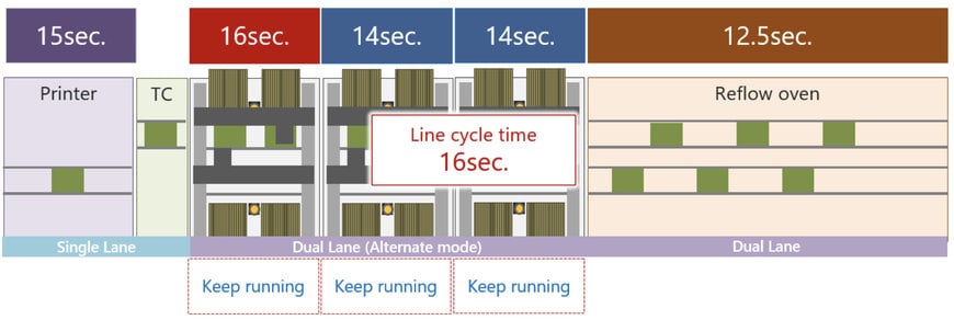
Faster cycle time with dual-lane reflow and component mounting. All mounter heads are fully utilized.
The longest of the mounting processes defines the overall line cycle time. Although this mounter is effectively limiting the line performance, the cycle time is significantly improved compared to the example in figure 1 and all mounting heads are fully utilized; hence, no investment in mounting performance is being wasted in this example.
A single-lane dual-stage mounter as shown in figure 3 can deliver boards into dual-lane reflow using a traversing unit and also allows faster cycle time than a dual-lane setup. The dual-stage machine also gives the flexibility to revert to single-stage operation to populate smaller boards that have a shorter cycle time. A software tool like Yamaha’s line optimizer can automatically calculate and apply the most effective settings. The table summarizes the typical options for SMT managers looking to upgrade the cycle time of their lines.
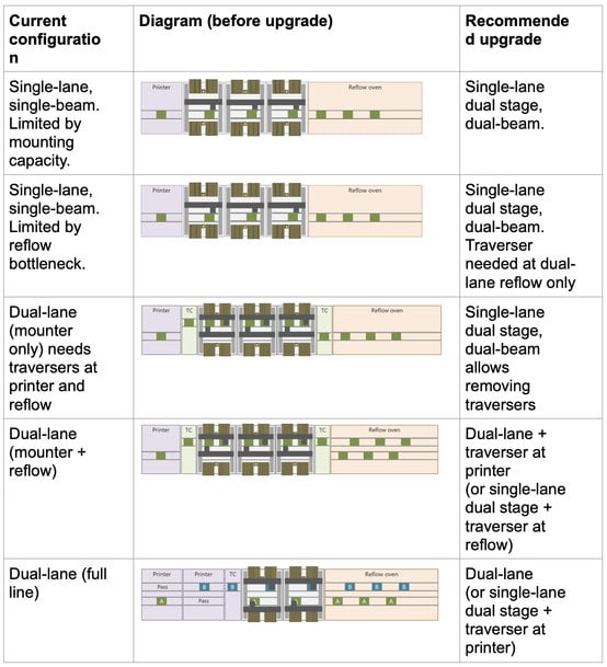
Guidelines for cycle time improvement.
Conclusion
Every SMT line contains a bottleneck. When the time comes to upgrade, understanding its location is vital to direct investment appropriately places are made. When the mounting cycle time is long, dual-stage placement is a strong option. When the cycle time is short, investing in dual-lane reflow can be more effective.
Introducing dual-lane automation into a single-lane line is not a straightforward upgrade and comes with compromises on throughput and feeder availability. If floorspace is limited and other single-lane equipment is to stay, a dual-stage single-lane mounter can deliver a convenient and cost-effective boost to productivity.
www.yamaha-motor-robotics.com

